14-Aug-2026

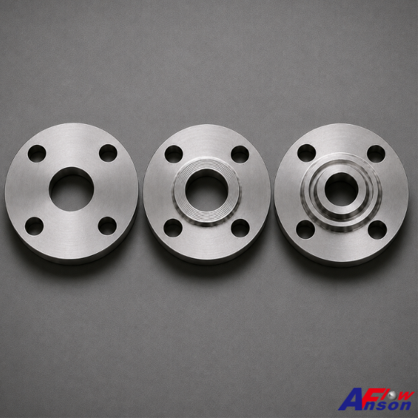
When engineers specify a flanged valve, most of the attention goes to body material, pressure class, and trim. The flange face — the finished surface where the gasket actually seals — often gets treated as an afterthought. Yet it is exactly where a joint either leaks or holds. Pick a face that is wrong for the pressure, the temperature, or the mating flange, and you end up with either a leak path or money spent on capability you will never use. Here are the three flange facings you will actually meet in the field, and where each one belongs. Raised Face (RF) — the default workhorse The RF is the most common facing in process piping. A small raised surface — 1.6 mm (1/16") on Class 150 and 300, 6.4 mm (1/4") on Class 400 and above — concentrates the bolt load onto a defined gasket area. It works with flat ring or spiral-wound gaskets and covers the vast majority of general service from Class 150 to 2500. Use it for: general water, oil, gas, steam, and process service at moderate pressure and temperature — the sensible default unless something specific pushes you off it. Flat Face (FF) — for cast iron and low pressure An FF flange mates across its whole face with a full-face gasket. Its main job is to protect brittle mating flanges: bolting a raised face against a cast-iron flange can crack it as the studs pull the raised faces together, so equipment like cast-iron pumps and low-pressure vessels is specified FF. Use it for: connections to cast-iron or bronze equipment, and low-pressure Class 125/150 utility service. Ring-Type Joint (RTJ) — high pressure, high temperature, critical service An RTJ has a machined groove that seats a solid metal ring gasket (oval or octagonal). Made up by the bolt load, the ring deforms into the groove to form a metal-to-metal seal — the most leak-tight facing in common use, and the standard choice where failure is not an option. For the highest-pressure and wellhead duty, pressure-energized RX and BX rings take the same principle further. Use it for: Class 900, 1500, and 2500; high-temperature service; and critical hydrocarbon duty — wellheads, high-pressure gas, refinery hot lines. How to Choose — the Short Version Facing Typical class Seal Best for FF 125 / 150 Full-face gasket Cast-iron equipment, low pressure RF 150 – 2500 Flat / spiral-wound gasket General process — the default RTJ 900 – 2500 Metal ring, metal-to-metal High P/T, critical hydrocarbon Two rules of thumb tie it together: as pressure and temperature climb, you move FF → RF → RTJ; and always match the mating flange — the same face, the same finish, and for RTJ the same ring number. Don't Forget the Surface Finish Even a correct RF leaks if its finish is wrong for the gasket. RF faces carry a defined serrated finish — commonly 125–250 µin AARH (Ra ≈ 3.2–6.3 µm) — that gives a spiral-wound or sheet gasket something to bite into. Too smooth and the gasket slips; too rough and it will not seal. It is a small spec that quietly decides whether the joint holds. Anson Flow Flanged Valves Anson Flow supplies flanged gate, globe, ball, and check valves with RF or RTJ facings to ASME B16.5 / B16.47, dimensioned and rated to ASME B16.34 (and API 6D where applicable) — so the valve's face, class, and finish match the flange it bolts to. Tell us your class, service, and the mating flange facing, and our engineering team will confirm the right face and finish for the joint. 📩 sales@ansonflow.com 🌐 https://www.ansonflow.com

07-Aug-2026

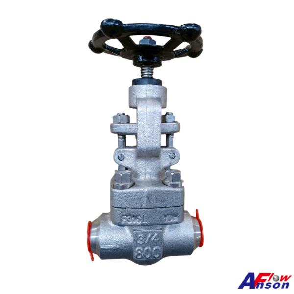
Every gate and globe valve has to solve one quiet but critical problem: how to seal the joint between the body and the bonnet — the pressure boundary that also has to open back up whenever the valve needs service. How that joint is made determines the valve's pressure capability, its maintainability, and how safely it holds over years of thermal cycling. There are several ways to close a bonnet — screwed, union, welded, pressure-seal — but for the vast majority of industrial gate and globe valves, one design has become the default: the bolted bonnet. Here is why it earns that position. 1. Built to Be Serviced, Not Scrapped The internals of a gate or globe valve are wear parts — the gate's wedge and seats, the globe's disc and seat, and the stem and packing common to both. Over a long service life they need inspection, re-machining, or replacement. A bolted bonnet makes that routine. Undo the bonnet bolts and the entire trim is accessible: lap the seats, replace the wedge or disc, renew the stem or packing, and re-torque. Compare that with a welded bonnet, which seals permanently but turns any internal wear into a scrap-the-valve event. This matters even more on globe valves, which are frequently used for throttling and repeated operation — duties that wear the disc and seat faster and make easy access essential. Over the life of a plant, a serviceable valve is almost always the lower total cost, and the bolted bonnet is what makes service possible. 2. High Pressure and Temperature, Held Predictably The bolted joint is a studded, gasketed pressure boundary. Bolt preload clamps the bonnet to the body across a defined gasket, and that clamp load is what contains the line pressure — not thread engagement, and not an operator's feel on a wrench. Because the load is set by torqued studs, it is predictable, inspectable, and repeatable. That is what lets bolted-bonnet gate and globe valves cover the full industrial range — from ANSI Class 150 up to Class 2500 — and ride out the repeated thermal cycling of steam, process, and pipeline service without loosening. 3. A Defined, Replaceable Seal The body-bonnet joint seals on a discrete gasket chosen for the duty: sheet gaskets at lower classes, spiral-wound or ring-joint metallic gaskets at higher pressures. This matters because the sealing element is a known, specified, replaceable part — not an assumption. When the bonnet is opened for service, the gasket is simply renewed, and the joint returns to a defined sealing condition every time. Screwed and union bonnets cannot offer the same combination of high-pressure integrity and clean re-sealing. 4. Standardized, Certified, and Easy to Specify The bolted bonnet is the joint the governing standards are written around. Cast-steel gate valves are built to API 600 and forged-steel to API 602; steel globe valves to B16.34 — all with pressure-temperature ratings to ASME B16.34 and shell/seat testing to API 598. For a buyer or engineer, that means a bolted-bonnet gate or globe valve is interchangeable, inspectable, and globally accepted — you specify a class and a standard, and you know exactly what you are getting. It is the path of least risk in procurement. 5. A Platform for Variants Because the bolted bonnet is a modular, bolted structure, it adapts cleanly to demanding service. The clearest example is cryogenic duty: an extended bolted bonnet moves the stem packing away from the cold zone, keeping the seal warm and workable. Both gate and globe valves take the same variant — it simply bolts onto the proven architecture. The AnsonFlow Gate & Globe Valve Range Model Type & Design Range AF-GTE Gate · cast steel · bolted bonnet · API 600 ANSI 150–2500 · PN10–40 · JIS 10K/20K · 1/2"–36" AF-GTF Gate · forged steel · bolted bonnet · API 602 ANSI 150–1500 · 1/2"–2" AF-GTC Gate · cryogenic · extended bolted bonnet 1/4"–3" AF-GVE Globe · cast steel · bolted bonnet · B16.34 ANSI 150–900 · PN10–40 · JIS 10K/20K · 1/2"–12" AF-GVF Globe · forged steel · bolted bonnet · API 602 / BS 5352 ANSI 150–2500 · 1/2"–2" AF-GVC Globe · cryogenic · extended bolted bonnet ANSI 150/300 · JIS 10K/20K · 1/2"–6" All are built to the bolted-bonnet standards that make gate and globe valves serviceable, certifiable, and reliable across oil and gas, petrochemical, power, and process service. Tell us your class, size, material, and service conditions, and our engineering team will help you specify the right configuration. 📩 sales@ansonflow.com 🌐 https://www.ansonflow.com/product-category/check-globe-gate-n

24-Jul-2026

Both of Anson Flow's ball valve locking handle designs accept a padlock. Both meet Lockout / Tagout (LOTO) requirements. So what's the difference — and when does it matter? The short answer: one of them has an added lock plate. That single component changes how the handle behaves in the field, and picking the right one comes down to what you're actually trying to prevent. Here's how to tell them apart. Why Ball Valve Handles Need to Lock Any plant running a Lockout / Tagout program needs valves that can be physically secured during maintenance — not just tagged. That's the baseline function. But there's a second, quieter problem: inadvertent operation. Valves get bumped by passing forklifts. Handles get grabbed by mistake in the dark. Vibration on a compressor skid slowly walks a lever out of position. These aren't LOTO events — they're daily wear-and-tear — but the consequences can be just as serious. Different handle designs address these two problems differently. Design 1: Handle with Lock Plate A separate stainless steel lock plate sits at the base of the handle. It does two jobs: Padlock-ready for full LOTO — a padlock physically blocks handle rotation, just like any other locking handle Anti-tamper position hold — even without a padlock, the plate mechanically resists casual bumping, incidental contact, and low-level vibration, keeping the handle where the operator left it The extra mechanism means a more robust presence on the floor. The plate is visible, engineered, and clearly a safety feature. Best for: High-traffic zones where valves are exposed to accidental contact Vibration-prone installations (rotating equipment, compressor skids) Applications where you want a mechanical safeguard against handle drift between LOTO events, not just during them Group LOTO situations where the plate can accept multiple padlocks for multi-worker isolation Design 2: Standard Padlock-Ready Handle A flat steel handle without a separate lock plate. A padlock secures the handle against the valve body directly — no additional mechanism required beyond the handle itself. Best for: Applications where inadvertent operation isn't a significant risk, and the handle is used strictly for controlled operation and formal LOTO events Installations that benefit from a single-component design with fewer parts to install, inspect, or specify Standardized LOTO programs where the padlock alone provides sufficient protection between events Side-by-Side Comparison   Lock Plate Handle Standard Padlock-Ready Handle Padlock / LOTO support ✓ ✓ Anti-tamper position hold (no padlock needed) ✓ Not designed for this Group lockout (multiple padlocks) Yes, plate accommodates Typically single padlock Component count Handle + lock plate Integrated handle Design profile Robust — visible engineered mechanism Streamlined — single-component Best for Anti-tamper + LOTO combined Clean LOTO in low-risk zones Neither is a higher grade than the other. They solve different problems, and Anson Flow specifies the appropriate handle style based on the valve model and typical application — not on price tier. How to Choose in 30 Seconds 1. Is inadvertent handle movement a real risk in your installation? Yes (high-traffic, vibration, contractor-heavy environment) → Lock Plate handle No (protected pipe rack, dedicated operators) → Either works 2. Do you need group lockout with multiple padlocks on a single valve? Yes → Lock Plate handle No → Either works 3. Is a compact, single-component handle important for your installation? Yes → Standard Padlock-Ready handle No → Either works FAQ Q: Do both handle designs comply with LOTO regulations? Yes. Both accept standard padlocks and physically block handle rotation when locked. The choice between them is about additional protection (anti-tamper) and application fit, not baseline LOTO compliance. Q: Can I choose either handle design regardless of valve model? Not always. Different Anson Flow ball valve models have their own factory-matched handle configurations based on size, torque requirements, and application category. For your specific model, contact our sales team to confirm what's available. Q: What is the "lock plate" actually for if the handle already has a padlock hole? The lock plate provides mechanical resistance to handle movement without a padlock installed — protecting against accidental bumping, vibration walking, or unauthorized casual operation. It's a second layer of protection between formal LOTO events. Talk to Us Before You Specify Which locking handle style ships with your valve depends on the specific Anson Flow model, size, and configuration you're specifying. If your application involves high traffic, vibration exposure, or specific LOTO padlock standards, let us know early — we'll match you to the right handle configuration and provide the documentation your safety auditors will look for. Both handle styles are available across our ball valve range, including our fire-safe series, sanitary series, and general-service ball valves. 📩 Talk to our engineering team: sales@ansonflow.com 🌐 Explore our full range: www.ansonflow.com

13-Jul-2026

Ask any plant safety engineer for the most common valve incident, and the answer is rarely dramatic. It's not a burst body or a fire-melted seat — it's a manual valve that was simply left open when it should have been closed. A sampling valve nobody shut. A drain cracked open after a shift change. A loading line walked away from while still flowing. None of these are equipment failures. They come from one design assumption we rarely question: that a conventional lever valve stays wherever the last person left it. The Spring Return Handle (SRH) removes that assumption — it makes closed the default state of the valve. A Different Kind of Safety: Designing Out Human Error Most valve safety features protect against what the fluid can do — pressure containment, Fire-safe, Anti-static. All of them assume the valve is already in the right position. A Spring Return Handle protects against what the operator forgets to do. The principle is "dead-man" operation: ·         The valve is open only while someone is physically holding the handle. ·         Release it — on purpose, by accident, or by walking away — and an internal spring drives it closed automatically. This makes the valve mechanically normally-closed. Flow isn't the resting state someone has to remember to stop; stopped is the resting state, and flow exists only while an operator is present and engaged. The single largest cause of manual-valve incidents — human error — isn't trained against or proceduralized. It's designed out of the mechanism. Fail-Safe Closure — No Air, No Power, No Actuator There's already a known way to get normally-closed behaviour: a spring-return actuator that fails closed on loss of signal. It works, but it brings an air supply, tubing, solenoids, and a control loop with it — far more than a sampling tap, manual drain, or hose station needs. The SRH delivers fail-safe, normally-closed operation on a purely manual valve — no air, no electricity, no actuator to specify or service. The "fail-safe signal" is simply the operator's hand leaving the lever. And with roughly 3× the torque efficiency of a conventional handle, holding it open stays practical rather than something operators try to defeat. Where the "Must Not Stay Open" Logic Belongs SRH isn't for every valve — a process isolation valve meant to stay open for months is the wrong candidate. It earns its place wherever open should be a brief, supervised, momentary state: ·         Sampling and testing points — flow only while the sample is drawn. ·         Fuel handling, loading, and transfer — never left flowing unattended. ·         Drain, vent, and blowdown — momentary open, guaranteed re-close. ·         Batch dosing and manual filling — flow tied to operator presence. ·         Marine, offshore, and fire-protection systems — where predictable default states are non-negotiable. Across oil and gas, chemical, pharma and food, and water treatment, these are exactly the points where "someone left it open" becomes a spill, a cross-contamination event, or a reportable incident. The AnsonFlow SRH Series Model Base Valve AF-SRH Core spring-return handle on Anson Flow's ISO 5211 valve platforms AF-23 Compact two-way ball valves AF-35 3-piece ball valves — serviceable process lines; API 607 fire-safe AF-51 Flanged ball valves; API 607 fire-safe versions available Each adds automatic spring-return (dead-man) closure with ~3× torque efficiency on ISO 5211 two-way and flanged ball valves — fail-safe operation specified simply by choosing the spring handle in place of a standard lever. And on the AF-35 and AF-51, that operational safeguard can sit on top of an API 607 fire-safe base valve — pairing dead-man closure with certified fire performance on a single valve. Procedures and training ask people to remember. A Spring Return Handle asks nothing — it just makes closed the state the valve returns to on its own. 📩 sales@ansonflow.com 🌐 https://www.ansonflow.com/product-category/spring-return-handle

12-Jun-2026

In pipeline systems for petrochemicals, food processing, or specialty chemicals, the "temperature" of the fluid is often the critical factor determining the success of a production line. When media inside the pipeline (such as asphalt, liquid sulfur, high-viscosity resins, or chocolate) experience a drop in ambient temperature, they are highly prone to increased viscosity, crystallization, or even severe solidification. This not only damages the pipeline but also leads to costly, unplanned downtime. To solve this major pain point, the Heat Jacketed Valve has become an indispensable line of defense in industrial fluid control. Today, we will take a deep dive into one of Anson Flow's flagship products—the AF-S1J Steam Jacketed Ball Valve—to uncover the physics and mechanics it uses to perfectly maintain thermal balance within your piping system. How Does It Retain Heat? Unveiling the Magic of Heat Exchange A heat jacketed valve doesn't generate heat on its own; instead, it relies on an ingenious heat exchange structure to provide precise temperature control. Taking the AF-S1J as an example, engineers have precision-welded an additional metal shell around the exterior of a standard ball valve, creating a completely sealed "jacket" space. Think of this design as putting a custom-fitted thermal coat on the valve. ·         Independent Heating Circulation Loop: The jacket itself features dedicated inlet and outlet ports. Plant engineers can inject an external heating medium, such as high-temperature steam or thermal oil, directly into this isolated space. ·         Omnidirectional Heat Transfer: As the high-temperature medium continuously circulates within the jacket, thermal energy is evenly and persistently conducted through the metal valve body into the internal fluid. This "wraparound" heat transfer ensures that when the fluid passes through the valve—typically the node in a pipeline most susceptible to pressure drops and heat loss—it remains at its optimal operating temperature and fluidity, thoroughly eliminating the risk of dead-zone solidification. Flexible Configurations and Core Advantages of the AF-S1J Series When facing complex and variable pipeline designs, a single specification rarely fits all needs. The standout feature of the AF-S1J series is its exceptional configuration flexibility: 1.    Support for Multiple Structures (1-Piece / 2-Piece / 3-Way): l  1-Piece & 2-Piece: Ideal for standard straight-line shut-off and opening, featuring a compact structure that is easy to install and maintain. l  3-Way: Perfectly handles fluid diversion and mixing requirements while ensuring absolute temperature consistency during flow direction changes. 2.    Seamless Welding Process & Rigorous Pressure Design: The biggest nightmare for a jacketed valve is internal or external leakage from the jacket. Our precision welding process undergoes rigorous testing to ensure a flawless joint between the jacket and the valve body. This not only guarantees outstanding pressure resistance but also maximizes the circulation efficiency of the heating medium. 3.    Material Traceability & International Standard Compliance: In global supply chains, quality traceability is paramount. Every batch of valves leaving our facility comes with a complete Material Test Report (MTR) and fully complies with mainstream international standards. Whether you are supplying the stringent Japanese market or outfitting advanced facilities in Europe and the US, a product with complete certifications and precise manufacturing provides ultimate peace of mind for procurement and engineering teams. Ensuring Smooth Processes & On-Time Delivery In international B2B operations, stable logistics and delivery times are just as critical as exceptional product quality. Rooted in Taiwan's precision manufacturing excellence, we deeply understand how crucial time is to your system operations. Whether you have an urgent order or a special project requirement, we possess the agile scheduling capabilities to ensure that even high-spec or custom jacketed valves are delivered to you right on schedule. Upgrade Your Fluid Control System Today Fluid control allows for zero compromises. Let Anson Flow's AF-S1J Steam Jacketed Ball Valve be the most reliable guardian of your manufacturing process. Ready to eliminate pipeline blockages, lower pump energy consumption, and optimize your system's efficiency? 🔹 Explore the detailed specifications of the AF-S1J on our website. 🔹 Contact Anson Flow’s Expert Engineering Team for a customized quote at: sales@ansonflow.com

29-May-2026

When specifying valves for a natural gas pipeline, there's one question that engineers, buyers, and auditors all ask — but the answer is rarely as simple as it sounds: "Is this valve suitable for my natural gas application?" Answering that question requires looking beyond any single standard. Natural gas is both a high-pressure and a flammable fluid, which means a valve that can be safely deployed in a natural gas line must satisfy three layers of safety design: 1.    Pressure containment — the valve body must not fail structurally at working pressure (covered by PED 2014/68/EU and equivalent standards) 2.    Sealing integrity in a fire — the valve must continue to shut off gas even when an external fire occurs (covered by Fire-safe design) 3.    Ignition prevention in flammable atmospheres — the valve itself must not become an ignition source (covered by Anti-static design) Each layer has its own regulatory framework, and none of them can be skipped. This article walks through all three, the standards that govern them, and how Anson Flow's Firesafe series integrates the full set of requirements.   1. Layer One: Pressure Containment — PED and Related Standards PED (Pressure Equipment Directive 2014/68/EU) is the EU's mandatory directive for pressure equipment. It governs the structural safety of valves, vessels, and piping at their specified pressure and temperature, covering: ·         Material selection and metallurgical certification ·         Wall thickness and pressure design calculations ·         Welding procedures and welder qualifications ·         Factory hydrostatic testing ·         CE marking and technical documentation A valve holding PED certification means it will not rupture under normal working pressure — the baseline for any natural gas application, but not the only requirement. Other commonly referenced standards in this layer include ASME B16.34 (pressure-temperature ratings, widely used on North American pipelines) and AD2000 (the German pressure equipment code). But pressure containment only addresses one thing: that the valve body itself doesn't fail structurally. It cannot speak to sealing performance during a fire, and it cannot speak to ignition risk in flammable atmospheres. Both of those require their own layer of regulation.   2. Layer Two: Sealing Integrity in a Fire — Fire-safe Design If a fire breaks out near the pipeline and the valve's PTFE soft seat melts and loses its seal, natural gas will continue to escape uncontrolled through the failed valve — turning the fire scene into an explosion continuously fed by natural gas. This is why valves in natural gas, oil refining, petrochemical, and offshore service almost universally require Fire-safe design: ·         When the soft seat burns away, the ball drops onto a metal-to-metal secondary seat, maintaining basic shutoff function ·         Body seals are upgraded to graphite or expanded graphite gaskets that do not melt at high temperature ·         The complete valve must pass API 607 / ISO 10497 / BS 6755 Part 2 fire-test protocols (typical test: a 1027 °C flame applied continuously for 30 minutes, with leakage measured under specified limits within 10 minutes after the flame is extinguished) The point of Fire-safe is not "the valve won't get burned" — it's "even if it does get burned, gas will not continue to escape and feed the fire."   3. Layer Three: Ignition Prevention in Flammable Atmospheres — Anti-static Design When natural gas flows through a valve at high velocity, friction between the gas molecules and the ball, seat, and body surfaces generates static charge buildup. The problem is that PTFE seats are insulators — there is no natural conductive path between the ball and the valve body. If the accumulated charge discharges as a spark, and the surrounding atmosphere contains flammable natural gas or volatile vapors, the result is ignition. This is why natural gas service requires valves with an Anti-static device: ·         A conductive spring or contact between the stem, ball, and body creates a deliberate electrical continuity path ·         The standard requirement: resistance from ball → stem → body must be ≤ 10⁹ Ω ·         In ATEX Zone 1 / IECEx Zone 1 areas (where flammable atmospheres are likely present), this is mandatory under the ATEX 2014/34/EU directive — not an option.   4. The Regulatory Matrix for Natural Gas Valves The standards above cover different layers, and in real specification work they should be treated as stacked requirements rather than alternatives: Standard What it covers Status PED 2014/68/EU Pressure containment (prevention of rupture) EU mandatory for pressure equipment ATEX 2014/34/EU Equipment used in explosive atmospheres (includes anti-static requirements) EU mandatory in Ex areas API 607 / ISO 10497 / BS 6755-2 Fire-safe burn testing Widely required across industry API 6D Dedicated standard for oil and gas pipeline valves (fire-safe + anti-static + full bore + bidirectional sealing) Frequently specified for long-distance gas transmission API 608 General standard for metal ball valves Foundation for design and testing NACE MR-0175 / ISO 15156 Anti-corrosion material requirements for sour gas (H₂S) service Mandatory in H₂S environments ASME B16.34 Pressure-temperature ratings for flanged valves Commonly used on American pipelines Specification tip: If a project spec lists only a single standard (e.g. PED alone, or API 607 alone), it's worth confirming a few application details before placing the order — whether the fluid is natural gas or another flammable medium, whether the installation site is an ATEX/IECEx Ex area, and whether the gas contains H₂S or other sour components. These conditions determine which standards must apply simultaneously.   5. Anson Flow Firesafe Series: Three Layers Integrated Our complete Firesafe ball valve range is designed with Fire-safe construction and an Anti-static device integrated together, covering applications from general natural gas distribution to sour gas service and offshore platforms: Application Recommended Model Key Reasons Threaded end, sour natural gas (H₂S) AF-280 NACE MR-0175 + API 607 High-pressure wellheads, transmission AF-291H 6000 PSI + Firesafe Automated process lines, serviceable AF-35 / AF-35M 3-piece + Firesafe Main gas pipelines, ANSI flanged AF-50F / AF-51F API 607 7th + Anti-static + full bore DIN-spec market main pipelines AF-52F / AF-53F DIN PN10–40 + Firesafe One-piece flanged, tight installation space AF-58F 1-piece strength + Firesafe   6. Anson Flow's Commitment to Natural Gas Customers There is no "should be enough" specification for natural gas — every standard in the matrix above corresponds to an incident that has actually happened in the field. Pressure containment, Fire-safe, and Anti-static are three layers that cannot be reduced to two, and a mature valve supplier should be able to integrate all three in a single valve and provide the corresponding certification documents. The Anson Flow Firesafe series, from material selection (WCB, CF8M, special alloys on request) through structural design to factory testing, is built to meet the most demanding requirements in oil and gas service. If your customers are working on natural gas transmission, oil refining, petrochemical plants, offshore platforms, LNG receiving terminals, or city gas distribution networks — we can help clarify the application environment, match the right model to the applicable regulations, and provide the full certification documentation to back it up.   Ready to Specify the Right Valve for Your Next Natural Gas Project? Share your application conditions with us — fluid composition (including any H₂S content), pressure and temperature, and the applicable standards (PED / ATEX / API 6D / NACE etc.) — and our engineering team will help match the most suitable model. 📩 Contact our experts: sales@ansonflow.com 🌐 Browse the Firesafe series: https://www.ansonflow.com/product-category/firesafe-valve